Archive for the ‘Solder’ Category

Electronics Assembly

Friday, August 21st, 2015

Rework and Touch-Up

Friday, August 21st, 2015

Indium Corporation manufactures a variety of materials for PCB rework, repair, and touch up, including flux-cored wire, liquid rework fluxes, and TACFluxes®.

Flux Cored Wire

Pb-Free SAC wireIndium Corporation has developed a range of flux-cored wire solutions to meet the needs of virtually every electronic assembly and rework operation from no-clean flux-cored wire for circuit board assembly to activated flux-cored wire for non-sensitive electronics and electrical applications.

No-clean fluxes include:

  • CW-807 halogen free for high reliability assemblies
  • CW-807M, which has a small addition of halogen activator for more difficult to solder assemblies
  • CW-807H for high temperature alloys
  • CW-501 is rosin (colophony) free and shows exceptional soldering on a wide range of assemblies
  • CW-802 is recommended only when no halogen is a must and the process is well-controlled

Activated fluxes include:

  • CW-201, a traditional RA type flux as defined by the legacy Mil-Spec QQ-S-571
  • CW-207 formulated using a blend of heat stable clear rosins
  • CW-209, which has twice the amount of halogen activator as CW-207
  • CW-501, rosin (colophony) free and has exceptionally effective soldering on a wide range of assemblies

Liquid Rework Fluxes

Flux PensLiquid rework fluxes are packaged in convenient pen dispensers, providing the optimal fluxing with no waste. Flux pens utilize a spring-loaded applicator tip to deliver a controlled amount of flux to the work surface. The user friendly pin-point application is deal for touch-up and light assembly work. Liquid fluxes include:

  • FP-500, a halogen-free flux that is compatible with both SnPb and Pb-free assemblies
  • NC-771, a halogen-free, low-residue, all-purpose flux that passes the SIR test in the un-reflowed state
  • FP-300, a water-soluble flux that is compatible with both SnPb and Pb-free assemblies

TACFluxes®

TACFluxTACFluxes® have a variety of uses including rework and repair of various electronics assemblies and components, SMT component attach (including BGAs and flip-chips), BGA ball attach, preform soldering, and virtually any application where flux is required. Indium Corporation manufactures a complete line of TACFlux®, which include no-clean, water-wash, and RMA-based fluxes.

Some of the most common TACFluxes® include:

  • TacFlux 089: no-clean flux for Pb-free alloys
  • TacFlux 089HF: a halogen-free, no-clean flux for Pb-free alloys
  • TacFlux 025: a water-soluble flux for Pb-free and SnPb alloys
  • TacFlux 020B: a halogen-free, no-clean flux for Pb-free alloy

Source: Indium Corporation, Clinton, NY

Low Temperature Alloy Solders

Friday, August 21st, 2015

Low temperature alloys, which typically contain indium or bismuth, melt at temperatures less than 180°C. These low-melting alloys are required for a wide variety of applications, including:

  1. Step soldering involving temperature sensitive components
  2. Soldering to molded interconnect device (MID) plastics
  3. Fusible alloys/fuse applications
  4. Mercury replacement
  5. Thermal and electrical conductivity

Step Soldering Involving Temperature Sensitive Components

Step soldering is the process of attaching components to a substrate in a series of steps where each step in the soldering process uses a lower reflow temperature than the step before it. Standard components are attached first and then temperature sensitive components (like LEDs) are done last. These temperature sensitive components reflow at temperatures less than 180°C.

Soldering To MID Plastics

Molded interconnect device (MID) plastics have been around for many years, but are becoming more popular in product design. MID plastics, which are formed into 3D shapes to increase the functionality and reduce overall weight of each product, are important in automotive and medical applications.

Fusible Alloys/Fuse Applications

Fusible alloys are valued for their relatively low-temperature melting point precision, as well as for their physical properties at room temperature.

Fusible alloys can be used for:

  • Fuses
  • Tube bending
  • Lens blocking
  • Wax pattern dies
  • Potting molds
  • Punch anchoring

Properties

Property Indalloy
117 158 160-190 217-440 255 281
Melting Point or Range Deg/F 117 158 160-190 217-440 255 281
Weight lbs/in3 .32 .339 .341 .343 .380 .315
Tensile Strength lbs/in2 5,400 5,990 5,400 13,000 6,400 8,000
Brinell Hardness No. 12 9.2 9 .19 10.2 22
Maximum Load
30 sec lbs/in2
10,000 9,000 16,000 8,000 15,000
Safe Load Sustained 300 300 300 300 500
Conductivity (Electrical) Compared with Pure Copper 3.34% 4.17% 4.27% 2.57% 1.75% 5.00%
Cumulative Growth and Shrinkage Time after Casting
2 min. +.0005 +.0025 -.0004 +.0008 -.0008 +.0007
6 min. +.0002 +.0027 -.0007 +.0014 -.0011 +.0007
30 min. .0000 +.0045 -.0009 +.0047 -.0010 +.0006
1 hr. -.0001 +.0051 .0000 +.0048 -.0008 +.0006
2 hr. -.0002 +.0051 +.0016 +.0048 -.0004 +.0006
5 hr. -.0002 +.0051 +.0018 +.0049 .0000 +.0005
500 hr. -.0002 +.0057 +.0025 +.0061 +.0022 +.0005

Mercury Replacement

Indium Corporation manufactures several alloys that have very low-melting points. These liquid-at-room-temperature alloys are finding increased uses in various applications as a replacement for the more toxic mercury. In addition, the vapor pressures of these alloys are substantially lower than mercury.

Thermal and Electrical Conductivity

Alloy systems that are liquid at room temperature have a high degree of thermal conductivity, far superior than ordinary non-metallic liquids. This allows for the use of these materials in specific heat-conducting applications, such as the heat dissipation of sensitive components during operation, machining, and/or manufacturing.

Other advantages of these liquid alloy systems are their inherent high densities and electrical conductivities. Typical applications for these materials include thermostats, switches, barometers, heat transfer systems, and thermal cooling and heating designs.

The table below lists available Indalloy® alloys which are liquid at room temperature.

Indalloy
Number
Liquidus C Solidus C Composition Density
lb/in3
Specific
Gravity
gm/cm3
Thermal
Conductivity
(W/mK)
Electrical
Resistivity
(10-8Ω-m)
46L 7.6 6.5 61.0Ga / 25.0In / 13.0Sn / 1.0Zn 0.2348 6.50 15* 33*
51E 10.7 10.7 66.5Ga / 20.5In / 13.0Sn 0.2348 6.50 16.51 28.91
51 16.3 10.7 62.5Ga / 21.5In / 16.0Sn 0.2348 6.50 16.51 28.91
60 15.7 15.7 75.5Ga / 24.5In 0.2294 6.35 20* 29.42
77 25.0 15.7 95Ga/5In 0.2220 6.15 25* 20*
14 29.78 29.78 100Ga 0.2131 5.904 28.13 14.854
* Estimated

References:

1 Geratherm Medical AG, Safety Data Sheet, 93/112/EC, 20042 Michael D. Dickey, et al., Eutectic Gallium-Indium (EGaIn): A Liquid Metal Alloy for the Formation of Stable Structures in Microchannels at Room Temperature, Advanced Functional Materials, 2008, 18, 1097–11043 C.Y.Ho, et al., Thermal Conductivity of the Elements, Journal of Physical Chemical Reference Data, Vol. 1. No 2, 1972.4 Charles Kittle, Introduction to Solid State Physics, 7th Ed., Wiley and Sons, 1996. 

Packaging for Liquid Metal Alloys 

Liquid metal alloys are shipped in polyethylene bottles.

Storage/Shelf Life for Liquid Metal Alloys

Unopened bottles have a guaranteed shelf life of one year. It is recommended that the volume be replaced with dry argon as the material is removed from the bottle. This will minimize any possibility of oxidation on the surface of the alloy. If the alloy has been stored below its melting point and has solidified, it should be remelted and thoroughly shaken or mixed before use.

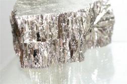
indium-bismuth_low_melting_temp-solder_252bismuth low-temperature melt solder


Source: Carol Gowan, Indium Solder Co.


Making Lead-free a Reality

Tuesday, August 18th, 2015

Lead-free fluxes used in solder paste, liquid flux for wave soldering, flux gels and wire solder are available today. These flux systems are designed to enhance the soldering process and are formulated to give excellent solder wetting performance with the added thermal stability of the chemistry, required with lead-free assembly. Traditional fluxes used with tin-lead alloys may not be adequate to circumvent the slower wetting of lead-free alloys and the higher temperatures normally associated with lead-free solders. Flux systems specifically formulated for lead-free soldering will require new activator packages and heat stable gelling and wetting agents to avoid solder defects. Due to the slower wetting and higher surface tension of many lead-free alloys, choosing the right flux for lead-free soldering will prevent the increase of solder defects and greatly assist in maintaining production yields. Typical defects, which can show an increase when transitioning to lead-free assembly are detailed below. These defects can be eliminated with proper flux selection and process control.

• Potential Defect Increase – Lead-free SMT Assembly
Bridging – Paste with poor hot slump behavior
Solder balls – Paste with poor slump properties
Tombstoning – Thermal differences across board
Non-wetting – Excessive preheating or inadequate flux activity
Poor wetting – Poor flux activity or excessive preheating
Solder Voids – Thermal profile too low, or inadequate flux chemistry
Solder beading – Paste with poor hot slump or excessive preheating
Potential Defects Increase – Lead-free Wave Soldering
Bridging – Flux deactivation during preheating or solder contact
Icicling – Flux too low in activity or preheating temperature to high
Solder Balls – Insufficient preheat or flux-solder mask incompatibility
Insufficient Hole-Fill – Flux activity too low, too low solids, or excessive preheat temperature or too low a contact time with molten solder

•Requirements for a Lead-Free Flux:
◦ Low-activation temperature
◦ Adequate shelf life
◦ High activity level
◦ High reliability
◦ Residues benign or easily remove with water if the paste is a water washable type

•Other Considerations for the Lead-free Flux :
◦ Is the paste for dispensing or printing?
◦ Note manufacturers use different types of activators for different alloys
◦ Select flux carefully to balance activation temperature with thermal profile
◦ What is the compatibility of the flux with the alloy selected?
◦ What are the reliability properties (SIR, electro-migration, corrosion)?

Considerations for Lead-free Solderpaste
•Important properties to consider during selection: ◦Solder Balling Test activity
◦ Wetting Test , specific finishes and solder atmosphere (air or nitrogen)
◦ Voiding Potential, lead-free alloys are more prone to solder voids
◦ Tack Life Over Time
◦ Stencil life and abandon time
◦ Cold Slump
◦ Hot Slump tested to higher temperatures 180-185 C ° .
◦ Shelf-life Testing

Properties to evaluate in-process:
◦Printability
◾Relax/Recovery
◾Print Speed
◾Durability

◦ Component Placement
◾ Drop back for tack

◦ Reflow
◾ Examine solder joint formation on a variety of leads and PWB finishes

• Properties to evaluate after reflow
◦ Thermal Shock
◦ Thermal Cycling
◦ Impact Resistance
◦ Reliability (SIR)

Technical Considerations for Wave Soldering Fluxes Designed for Lead-free Assembly
• Ability to be evenly applicable by spray, wave, or foam applications
• Activator package able to sustain higher preheating temperatures
• Able to be used with a variety of lead-free finishes, bare copper OSP, gold nickel, tin, silver immersion, tin-copper
• Sustained activity, the flux should remain active throughout the contact time with the molten solder, insuring good peel back of the solder
• Low dross potential, the flux must not react excessively with the molten solder as to create large amounts of dross
• The flux must not discolor or char at the higher soldering temperatures associated with lead-free wave soldering
• The flux should not decompose at the higher solder temperatures
• The flux residues must be benign if it is a no-clean flux, and easily washed in hot water if it is a water washable flux type

Technical Considerations for Lead-free Cored Solder Wires
•The flux should not spatter or fume excessively at the slightly higher soldering temperatures associated with lead-free soldering
•The flux should have activator systems designed to solder a variety of lead-free board and component finishes
•The flux must be active enough and remain active enough during tip contact to compensate for the reduced wetting of lead-free alloys
•The flux residues must be benign if it is a no-clean type, or easily removed in hot water if it is a water washable type cored solder
•The residue should not char or darken in color when using slightly higher solder tip temperatures

Source: Kester Solder Co.

How do you prepare a solder pot for lead-free solder?

Tuesday, August 18th, 2015

How do you ready a solder pot for lead-free solder?
It is important to first insure the solder is lead-free solder compatible. High tin alloys tend to leach iron causing dissolution of iron and solder contamination. The dissolution can advance to the point of causing micro-cracks and thinning of the walls, eventually resulting in a solder spill.

Materials that are lead-free solder compatible are:
• Titanium
• Cast iron
• Ceramic coatings
• Melonite coatings
• Specialty coatings, unique to the equipment maker

If a pot is lead-free compatible but contains leaded solder it can be cleaned before lead free solder is added. Cleaning is very important to avoid the introduction of lead. The limit required as per RoHS Directive is only 0.1%. Most lead-free solders will contain a small amount of lead in the range of 0.05%; there is little room for unintentional contamination.

A standard procedure for wave machine cleaning is detailed below:
1.Empty the pot completely
2. Drain any remain solder
3. After cooling use a scraper to gently remove any visible leaded solder
Avoid damage to the metal finish during scrap down
4.Clean ducts, baffles and impeller mechanism thoroughly
5. Clean conveyor chain and fingers with a steel brush, removing all lead-bearing solder particulates.
6. Fill machine with pure tin to clean any remaining leaded solder
7. Run system at 500º F for 2 hours, circulating the solder
8. Empty completely, removing all visible excesses
9. Refill with lead-free solder
10. Do an analysis for lead and iron after running pot for one hour

For dip pots and selective soldering pots, the cleaning is simpler but complete removal
of leaded solder is required and a tin fill is a less demanding process since the volume is
substantially less. A pot analysis for lead and iron is still required.
Note: If a tin wash is not performed it becomes imperative to remove all traces of leaded
solder in all parts of the solder pot area. The risk is highly increased in reference
to lead contamination. Tin washing is therefore preferred
About the author:

Source: Peter Biocca, Senior Market Development Engineer with Kester Inc.

Kester “44” Flux Residues

Tuesday, August 18th, 2015

Kester “44” Flux Residues
Are 44 flux residues harmful to an assembly? The 44 flux residues are non-conductive and non-corrosive. Residue removal would normally be for cosmetic reasons. If the assembly is in a heated environment and sees temperatures of over 160°F the flux residues will re-melt. When liquid (at high temperatures) the residues are conductive.

Soldering Thermocouple Wires

Tuesday, August 18th, 2015

Soldering Thermocouple Wires
Thermocouple materials are not solderable. It is possible to surround the thermocouple wire (encapsulate it) with solder but you cannot make a metallurgical bond to it. It is important to note that even if you could solder the two wires back together the thermocouple still will not work. A thermocouple works by measuring the change in resistance of the two dissimilar metals joined in the welded bead. If one were to join the metals with a solder inter-connect the thermocouple would give meaningless numbers. The way to fix a broken thermocouple is to re-weld the thermocouple bead. If you wish to attach a thermocouple to a printed circuit board for reflow profiling, you can use a high temperature alloy to encapsulate it or use a cyano-acrylate adhesive to stick it to the board.

Soldering to Aluminum

Tuesday, August 18th, 2015

Soldering to Aluminum
Aluminum is an extremely difficult metal to solder to. We do not have any products for soldering to aluminum.

Soldering to Gold

Tuesday, August 18th, 2015

There are many things that can go wrong when soldering to gold plate over nickel surfaces. First of all, we know that gold and solder are not good friends, as any time solder comes into contact with gold, something seems to go wrong. Either the solder bonds to the gold and eventually pulls off as the tin and gold cross-migrate, leaving
voids; or the solder completely removes the gold and is expected to bond to the metal which was under the gold.

If the gold is thicker than 40-50 micro-inches, the solder most likely may not dissolve all the gold and will bond to it. The solder will be dull-looking and, if the gold content in the solder exceeds about 5%, the solder joint will be brittle.
If the gold is thin, less than 20 micro-inches, it easily dissolves into the solder, making the solder joint look grainy. If the metal that was under the gold is not oxidized, the gold-contaminated solder will bond to it. However, as gold plates usually in a columnar structure, the gold should be at least 10 micro-inches thick to protect the base metal (in this case, nickel) from oxidation.

There are a couple of problems with nickel. If the nickel plate is electroless, quite often the plating bath contains phosphorous which codeposits with the nickel. We have found in the semiconductor industry that the phosphorous content in the nickel plating must be less than about 8% for the nickel to be solderable. If the nickel is applied by electroplating, it is possible for Ni(OH)2 to precipitate with the nickel plating. If the
nickel is not properly activated by acid rinsing before the gold plating is applied, it will not solder when the gold is dissolved away into the solder. In effect, the gold contaminated solder may stick to some clean areas of the nickel. Another possibility is the codeposition of carbon with the nickel, another contamination that could cause solder not to bond.

As is often the case, a company is able to get good soldering with a stronger flux. This
would point to the formation of nickel oxide that requires a stronger flux to remove. So,
we could surmise either thin gold did not provide protection for the nickel, or the gold
was plated over passive (unactivated) nickel.
Source: Kester Solder Co. January, 2005

Soldering to Stainless Steel

Tuesday, August 18th, 2015

One of the most frequently asked questions of Technical Services is, “How do I solder to
stainless steel?” Before discussing the “how to” aspect we need to first discuss the relation
between electronics and acid fluxes.

The use of acid fluxes for any electrical or electronic applications is not recommended!
This precaution is known throughout the industry. The clerk at the local hardware store will tell
you this, teachers in every level of electronic teaching will tell you this, and yet, many people
harbor a feeling that it is OK to use acid fluxes in electronics if you know the right secrets. There
are no secrets. During soldering, acid fluxes deposit zinc chloride in the solder and this salt can
not be removed. Exposure of the chloride to carbon dioxide and moisture initiates a corrosion
cycle. The chloride reacts with the lead in the solder, converting it to lead carbonate. After the
lead carbonate is formed, the chloride is free to attack more lead. The corrosion continues until
the solder joint dissolves.

What can assemblers do if they need to make an electrical connection to stainless steel? There
are one of two ways to make the connection. First settle for a mechanical connection. Using a
screw or rivet is perfectly adequate for most applications where stainless steel is involved. The
second way involves plating the stainless plated with a more solderable material such as copper
or nickel. The assembler can then solder to the newly plated stainless steel with standard
electronic solder and fluxes.

Now that we have eliminated any thought of soldering to stainless steel in an electronic
application we will look at how to solder to stainless steel for mechanical applications. Stainless
steel requires the use of special fluxs in order to acheive good adhesion of the solder to the
stainless steel. Typical acid core fluxes will not work on stainless. Kester has 817, which is
specially formulated for applications of soldering to stainless. Kester 817 must be used with solid
wire or it can be used in addition to acid core solder. Kester 817 flux is typically brushed on the
stainless and then the solder is reflowed using standard reflow procedures with an iron or a
torch. This concludes the discussion of soldering to stainless steel.

Source: David Scheiner – Technical Services Kester Solder Co.